


Choosing the right Spindle Motor Shaft can determine whether a machine runs smoothly or develops costly vibration. The shaft transfers rotational force, supports the tool holder, and influences accuracy at high speed. A small dimensional error may create visible chatter on a finished surface. Heat makes the problem worse. So does poor balancing.
Dr. Alexander H. Slocum, a respected precision machine design authority, once stated, “A machine tool is a system, not a collection of parts.” That principle fits spindle selection perfectly. Shaft material, diameter, runout, bearings, preload, cooling, and operating speed must work together. A shaft that looks strong on paper may still fail in real production. Sometimes, the overlooked detail is the real weakness.
This guide presents seven practical tips for selecting a Spindle Motor Shaft with greater confidence. It examines load capacity, rotational speed, stiffness, material quality, surface finish, dimensional accuracy, and supplier reliability. The discussion also considers maintenance access and the actual working environment. A clean laboratory test does not always represent a dusty workshop. Nor does the cheapest quotation prove better value.
Measure twice. Question assumptions.
The goal is not to choose the largest or most expensive shaft. It is to match the shaft precisely to the spindle motor, cutting force, duty cycle, and required finish. These decisions deserve evidence, not guesswork. Yet even experienced engineers can miss a thermal change or underestimate intermittent loading. Careful selection reduces that risk and supports stable, repeatable machining performance.
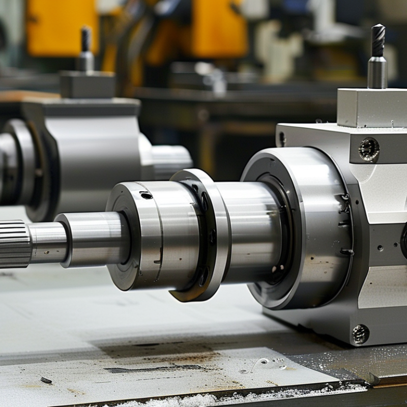
Choosing a spindle motor shaft starts with duty, not catalogue speed. Define whether the shaft will run continuously at 18,000–30,000 rpm, or only reach that speed briefly. Then match the required 1–5 kW power range to cutting load, acceleration, and thermal limits.
At 18,000 rpm, 1 kW produces about 0.53 Nm. At 30,000 rpm, 5 kW produces about 1.59 Nm. The formula is torque = 9,550 × power ÷ rpm. Small numbers matter at high speed.
Check seven practical points: shaft diameter, allowable runout, bearing arrangement, balance grade, cooling method, tool interface, and duty cycle. A larger shaft is not automatically safer. It can increase rotor inertia and slow acceleration. High-speed balancing should follow the applicable ISO 21940 requirements, while thermal behavior deserves testing under ISO 230-3 principles. This is where selection gets real.
The U.S. Department of Energy’s industrial motor assessments report that motor-driven systems use roughly 70% of industrial electricity, making efficiency and cooling more than paperwork.
Do not size the shaft from peak power alone. A five-minute overload can create heat that a short factory test never reveals. Measure housing temperature, vibration, current, and runout at several speed points.
Reports from the International Energy Agency repeatedly identify efficiency improvements in motor systems as a major industrial energy opportunity, but spindle losses are highly application-specific.
I would also question any design that relies on maximum rpm every day. That shortcut may work briefly, yet continuous operation near the limit can shorten bearing life and distort precision.
Tip 1: Measure the actual bearing bore and shaft diameter. Do not trust nominal drawings alone. ISO 286-2 defines tolerance limits for shaft classes such as h6 and k6. The correct fit depends on speed, temperature, and rotating load. A tight fit may prevent creep, but excessive interference can reduce bearing clearance.
Tip 2: Match the shaft diameter with the radial load path. ISO 281 calculates bearing rating life using L10 = (C/P)^p. For ball bearings, p equals 3. A small diameter can increase bending stress and shaft deflection. That movement may create uneven contact near the tool end. Industrial motor studies from the U.S. Department of Energy report that motor-driven systems consume more than half of industrial electricity. Efficient, stable rotation therefore matters beyond the bearing itself.
Tip 3: Check radial load ratings at the real operating speed. Use both dynamic rating C and static rating C0, referenced through ISO 76 and ISO 281. Compare calculated load with cutting forces, belt tension, and tool imbalance. Leave a practical margin. Engineers sometimes over-tighten a fit, then discover heat growth during a long cycle. I have seen this mistake survive because room-temperature inspection looked perfect.
Tip 4: Verify runout after assembly. A micrometer reading alone is not enough. Inspect the shaft, bearing seat, and tool interface together.
Tip 5: Recheck the design after temperature testing. ISO fit tables guide selection, but they cannot replace measured data from your actual spindle housing and duty cycle.
A spindle shaft needs more than high tensile strength. In practice, its surface faces constant contact, heat, vibration, and fine abrasive dust. Select a proven alloy steel grade, such as a chromium-molybdenum or nickel-chromium steel, with full material traceability. The U.S. Department of Energy’s 2022 Motor Systems Market Assessment estimates that motor-driven equipment consumes about 69% of industrial electricity in the United States. That figure shows why small efficiency losses and shaft defects deserve serious attention.
For wear resistance, specify a surface hardness above 58 HRC, measured under ASTM E18 procedures. This level can reduce scoring at bearing seats and tool interfaces. However, hardness alone is not a magic shield. ASM Handbook, Volume 4A, explains the practical trade-off between hardness, toughness, and heat-treatment control. A shaft hardened throughout may resist wear, yet crack under impact or sudden loading. Case hardening is often safer because it combines a hard outer layer with a tougher core. Check the effective case depth, not only the final HRC value.
Geometry still matters. A polished transition radius can reduce stress concentration near shoulders. Runout should be checked after heat treatment, because distortion is easy to underestimate. I would also request ultrasonic inspection and a certified hardness map. Some specifications look perfect on paper. Real shafts can still fail from poor grinding, residual stress, or incorrect tempering. Review operating speed, lubrication, fit tolerances, and cooling conditions before approving the steel grade.
Control runout below 5 μm for precision cutting applications by checking the shaft at the tool interface. Start with a hardened shaft and a precisely ground taper. The surface must be smooth. Even a tiny burr can shift the cutting edge and distort measurement results. Select a shaft with sufficient diameter and stiffness for the cutting load. A flexible shaft may pass a static test but deflect during high-speed milling.
Check bearing fit, preload, and shaft concentricity together. These factors directly affect radial runout. Measure with a calibrated indicator and a certified test bar, not only with a bare shaft. Record readings at several positions. A practical target is below 5 μm at the taper and below 3 μm near the tool holder when the application demands it.
Keep the assembly clean. One metal chip can matter. Balance the complete rotating assembly at its working speed, because vibration often appears after acceleration.
Control temperature before final inspection. Thermal growth can change shaft position by several micrometers. Allow the spindle to stabilize, then repeat the measurement. Do not trust one reading.
A common mistake is choosing an extremely stiff shaft while ignoring bearing quality and cooling behavior. That choice looks correct on paper, but it may create heat, noise, and shorter service life. Leave room for verification, because real cutting conditions are rarely perfect.
A spindle shaft must match its bearings, speed, load, and machining method. Check the bearing type, preload, lubrication method, and rated operating speed. Angular-contact bearings need careful preload control. Excessive preload creates heat, while insufficient preload allows vibration. Inspect shaft runout with a calibrated indicator near the tool interface. A reading that seems acceptable at low speed may change during thermal expansion. Check both.
Balance grade G2.5 is a useful requirement, but it does not guarantee smooth operation. Confirm the test speed, rotor configuration, and balancing method. The complete rotating assembly should be tested, including the shaft, holder, nut, and retention hardware. A perfectly balanced bare shaft can still vibrate after assembly. This detail is often missed.
Cooling deserves equal attention. Air cooling may suit light duty, while liquid or oil-air systems handle higher heat loads. Verify flow, filtration, sealing, and temperature monitoring. Keep coolant away from bearing cavities unless the design permits it.
Tool interface compatibility affects accuracy, safety, and setup time. Match the taper, gauge length, drawbar force, collet system, and maximum tool diameter. Confirm the shaft’s rated speed with the actual holder, not only the motor specification. Also check thread dimensions and retention features. One practical mistake is trusting drawings without measuring the existing interface. Manufacturing tolerances, worn holders, or incorrect gauges can change the result. Leave room for inspection, because real workshop conditions are rarely perfect.
5107 County Road C
Manitowoc, WI 54220
920-726-4526